 English
 Español
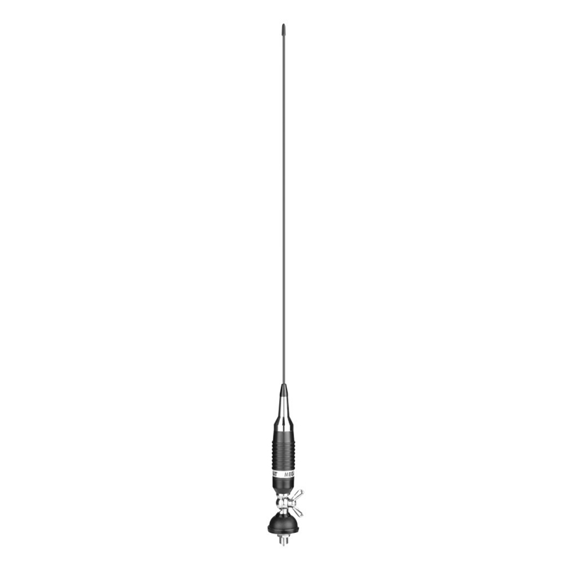
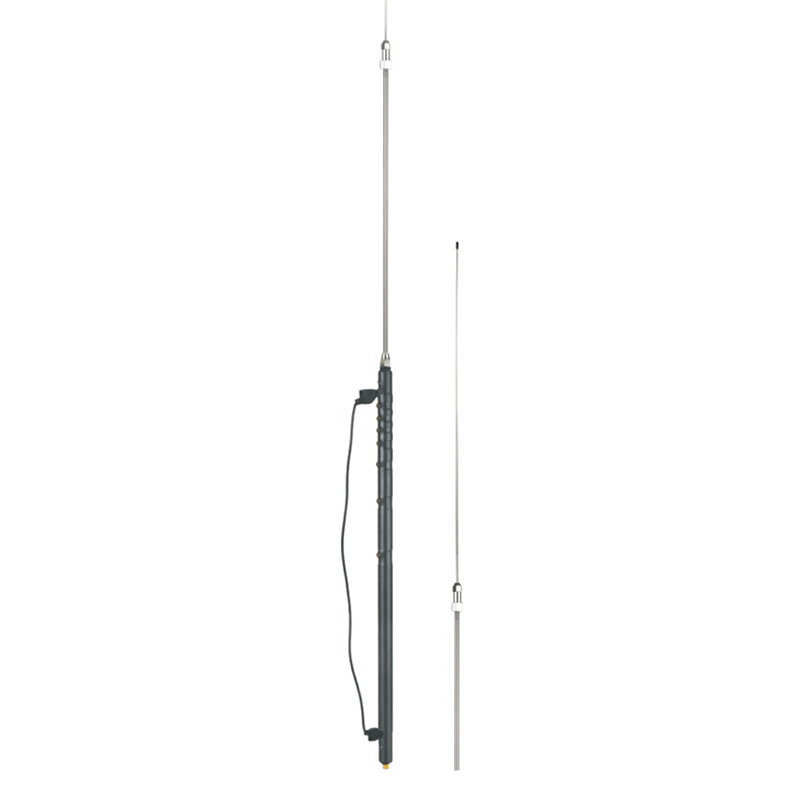
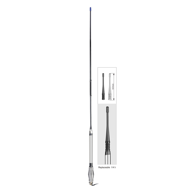
Frequency range: 26.5- 28MHz SWR: ≤1.2:1 Max. power: 35W continuous 250W Short time Bandwidth at S.W.R. 2:1: 1900KHz Impedance: 50ohm Whip length: 1200mm Adjustment: 0~90° Cable Length: RG58/157" Po...
See Details
Home / Customized Product / Industry news / Why does the ground plane design of CB Antenna affect signal transmission efficiency?
Why does the ground plane design of CB Antenna affect signal transmission efficiency?
In Citizens Band (CB) radio communications, the ground plane design of the antenna is often regarded as one of the core factors affecting signal transmission efficiency. Whether it is a vehicle-mounted antenna or a fixed base station, the interaction between the ground plane and the antenna directly determines the radiation direction, impedance matching and energy loss. Understanding the electromagnetic principles behind it can not only optimize communication quality, but also avoid performance bottlenecks caused by design errors.
The basic role of the ground plane: image theory and current loop
According to antenna theory, the ground plane forms a "virtual mirror" under the vertical monopole antenna (such as the common ¼ wavelength CB antenna) through the image principle, making the originally asymmetric antenna structure equivalent to a symmetrical dipole antenna. This equivalence extends the effective electrical length of the antenna and significantly affects its radiation resistance. For example, an ideal conductive ground plane can increase the radiation resistance of a ¼ wavelength antenna from about 36Ω to 50Ω, thereby achieving impedance matching with the coaxial cable and reducing the energy reflection caused by the standing wave ratio (VSWR).
However, if the ground plane is not conductive enough or the area is too small, the mirror effect will be weakened. Experiments show that when the metal roof area of the vehicle antenna is less than ¼ wavelength (about 2.7 meters in the CB band), the radiation resistance of the antenna will drop below 20Ω, resulting in up to 30% of the transmission power being wasted in the feeder in the form of heat loss.
Correlation between ground shape and radiation pattern
The geometric structure of the ground plane has a decisive influence on the radiation pattern. An ideal circular or square conductive plane can make the antenna form omnidirectional horizontal radiation, while a plane with insufficient size or irregular shape (such as the curved surface of the vehicle hood) will distort the current distribution and cause the radiation lobe to split. For example, when the vehicle antenna is installed at the rear of a truck, the signal is often tilted 15-20 degrees forward due to insufficient metal area at the rear of the vehicle body, reducing the rear communication distance.
In addition, the edge effect of the ground plane cannot be ignored. When the horizontal distance between the edge of the plane and the antenna is less than ¼ wavelength, the edge current will generate secondary radiation, which will interfere with the main radiation wave in phase. This phenomenon is particularly evident in the 28MHz frequency band, which may cause the signal attenuation at certain elevation angles to exceed 6dB.
Material selection and loss control
The conductive material of the ground plane directly affects the skin depth of high-frequency current. Taking the CB band as an example, the skin depth of copper is about 12μm, while the skin depth of galvanized steel is 35μm due to its high resistivity. Using a 0.5mm thick aluminum alloy plate can reduce conductor loss by about 18% compared to a steel plate. For mobile application scenarios, although carbon fiber composite materials are lightweight, if the resistance of their surface conductive coating exceeds 0.1Ω/□, the antenna efficiency will drop by more than 40%.
Optimization suggestions include: using a 2×2 meter aluminum grid ground grid for fixed base stations, expanding the current distribution of vehicle-mounted antennas with magnetic ground plates, or compensating for limited plane area by loading radial conductors. The actual measurement of the vector network analyzer (VNA) shows that adding 4 ¼ wavelength radial conductors can optimize the standing wave ratio of the vehicle-mounted antenna from 2.5:1 to 1.5:1, and increase the equivalent radiated power by 3dB.
The ground plane design of CB antenna is essentially a coupling problem between electromagnetic environment and physical structure. Only by taking the conductive area, shape symmetry, material parameters and installation position into consideration can the performance limitations of a single antenna element be overcome. With the popularization of electromagnetic simulation software, engineers can predict the impact of the ground plane before prototyping through three-dimensional field distribution simulation, thereby maximizing communication efficiency at a lower cost.
Related products
-
-
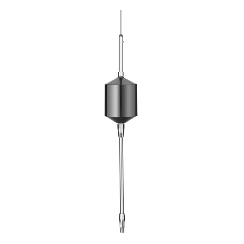
Type: 5/8λ Frequency range: 26.5-28MHz SWR: ≤1.2 Gain: >6dBi Bandwidth at S.W.R.2:1: 1300KHz Max power: 1000W Whip length: 1250mm Polarity: Vertical Connector: 3/8-24 Material: Copper Stainless ste...
See Details -

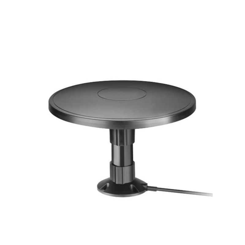
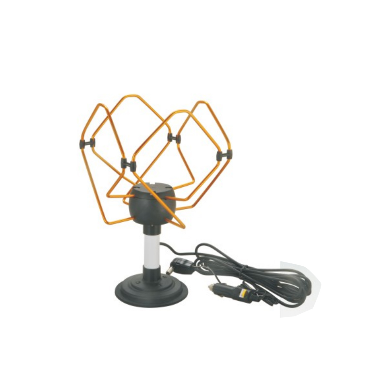
Electrical Specification Frequency Band: VHF, UHF Frequency: VHF: 174~230MHz, UHF: 470~862MHz Gain: 18±3dBi Work Voltage: 8~24V Impedance: 75ohm Radiation pattern: Omni-directional Coax Cable: 3C-2V, ...
See Details -
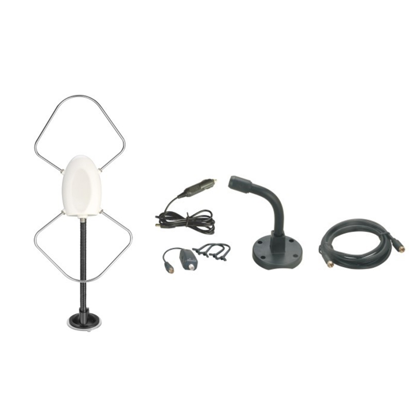
Electrical Specification Frequency Band: VHF, UHF Frequency: VHF: 174~230MHz UHF: 470~862MHz Gain: 18±3dBi Work Voltage: 8~24V Impedance: 75ohm Radiation pattern: Omni-directional Coax Cable: 3C-2V,...
See Details -
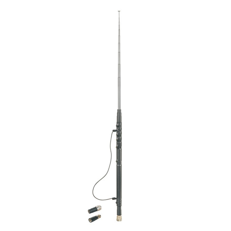
Band: 80,40,20,15, 10mts. Center frequency: 3.56, 7.05, 14.2, 21.1, 29MHz Connector: PL-259, 3/8-24 Impedance: 50ohm Whip Length: adjusted Material: Copper, Stainless Steel
See Details -

Band: 80, 40, 20, 15, 10, 6mts. Center frequency: 3.56, 7.05, 14.2, 21.1, 29, 50MHz Connector: UHF MALE(PL-259) Impedance: 50ohm Whip Length: adjusted Material: Copper, Stainless Steel
See Details -
Band: 80, 40, 30, 20, 17, 15, 10, 6mts. Center frequency: 3.56, 7.05, 10.1, 14.2, 18, 21.1, 29, 50MHz Connector: 3/8-24 Impedance: 50ohm Whip Length: adjusted Material: Copper, Stainless Steel
See Details -
Electrical Specification Frequency: UHF: 470~862MHz Gain: 18±3dBi Work Voltage: 8~24V Impedance: 50ohm Radiation pattern: Omni-directional Coax Cable: 3C-2V, L=4000mm Connector: TV or Customized Size:...
See Details -
Electrical Specification Frequency: 470~862MHz Gain: 10±2dBi Work Voltage: 8~24V Impedance: 50ohm Coax Cable: 3C-2V, L=4000mm Connector: TV or Customized Size: 330mm
See Details -
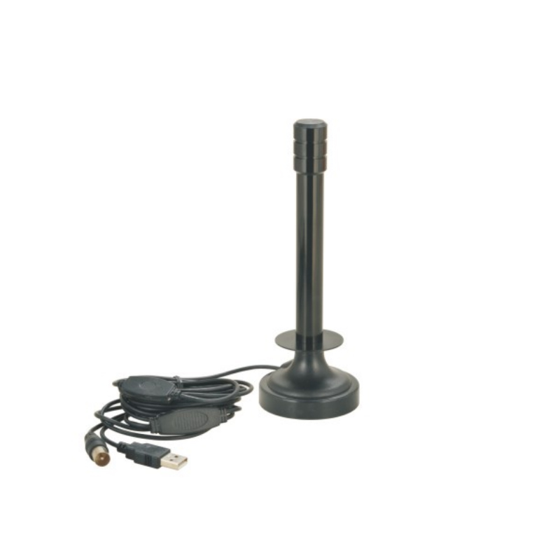
Electrical Specification Frequency: 470~862MHz Gain: 10±2dBi Work Voltage: 8~24V Impedance: 50ohmVSWR: ≤3:1 Coax Cable: RG174, L=3000mm Connector: USB, TV or Customized Size: 160mm
See Details -
Electrical Specification Frequency: 470~862MHz Gain: 10±2dBi Work Voltage: 8~24V Impedance: 50ohm Coax Cable: RG174, L=3000mm Connector: TV or Customized Size: 330mm
See Details -
Frequency: 476.42-477.40MHz Gain: 6.5 dB VSWR <1 .2: 1 Impedance: 50Ohms Radiation Pattern: Omni-directional Materials: Solid Fiberglass, Brass, stainless steel Antenna Length: 920mm Cable: RG58 C/...
See Details
Copyright © Shanghai Bodn Industrial Co., Ltd. All rights reserved. Wholesale Antennas Manufacturers OEM/ODM Antennas Company

Contact Us