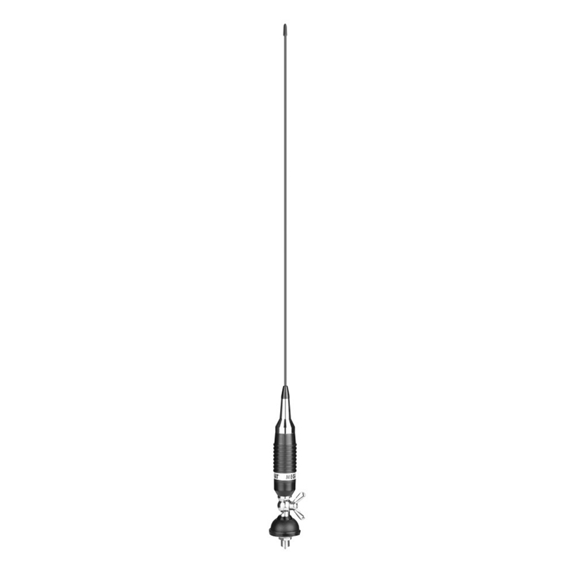
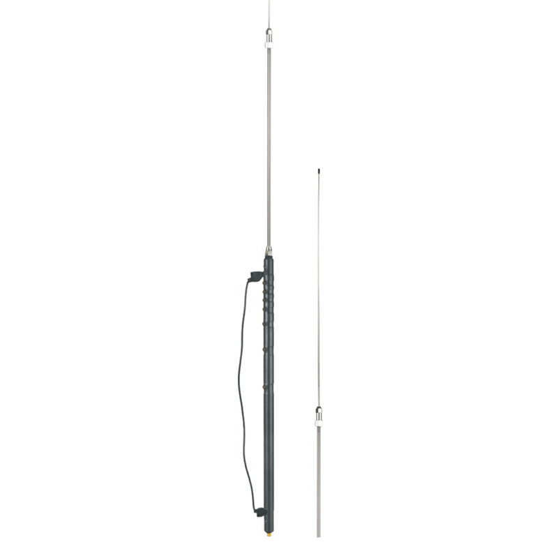
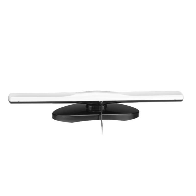
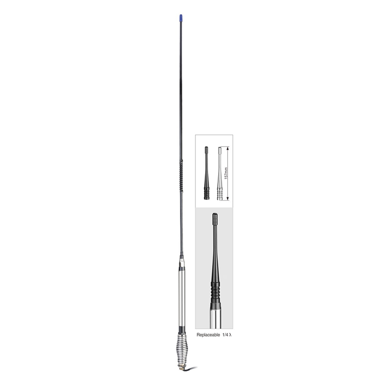
Frequency range: 26.5- 28MHz SWR: ≤1.2:1 Max. power: 35W continuous 250W Short time Bandwidth at S.W.R. 2:1: 1900KHz Impedance: 50ohm Whip length: 1200mm Adjustment: 0~90° Cable Length: RG58/157" Po...
See DetailsWhat are the impedance matching methods of CB Antenna at different frequencies?
The impedance matching methods of CB Antenna (communication broadcast antenna) at different frequencies can be mainly divided into two categories: changing impedance and adjusting the wavelength of the transmission line. The following are specific matching methods:
1. Changing impedance (lumped-circuit matching)
Series or parallel capacitors and inductors:
By connecting capacitors or inductors in series or in parallel with the antenna load, the impedance value of the load can be increased or decreased, so that it matches the characteristic impedance of the transmission line.
When designing a PCB antenna coil, the inductance, line width, number of turns and other parameters of the coil can be adjusted according to actual needs to approximately achieve the required impedance value.
Use matching circuit:
For specific chips (such as AS3911), you can refer to its design guide (such as "AS3911_AN01_Antenna_Design_Gui") to preliminarily determine the EMC (electromagnetic compatibility) and matching circuits.
Use a network analyzer to appropriately adjust the EMC and matching circuits so that the antenna resonates at the required frequency and matches the appropriate resistance value (such as 10 ohms and 50 ohms).
Using the Smith chart:
The Smith chart is a graphical tool for impedance matching. By adjusting the parameters of the matching circuit, you can find the point on the Smith chart that intersects the real axis.
2. Adjust the wavelength of the transmission line (transmission line matching)
Lengthen the transmission line:
Lengthen the transmission line from the load point to the source point, so that impedance matching can be achieved on the transmission line. This can be achieved by moving the dots on the chart in a counterclockwise direction along the center of the chart until you reach the circle with a resistance value of 1.Add capacitors or inductors:
After determining the length of the transmission line, you can add appropriate capacitors or inductors to further adjust the impedance to achieve the desired matching value.
Induction:
Impedance matching is the key to ensuring that the antenna transmits energy efficiently at a specific frequency. By changing the impedance and adjusting the wavelength of the transmission line, impedance matching between the antenna and the transmission line can be achieved. In practical applications, the appropriate impedance matching method can be selected according to the specific design and use requirements of the antenna. At the same time, graphical tools such as the Smith chart can make impedance matching design and debugging more convenient.

 English
 Español



Contact Us