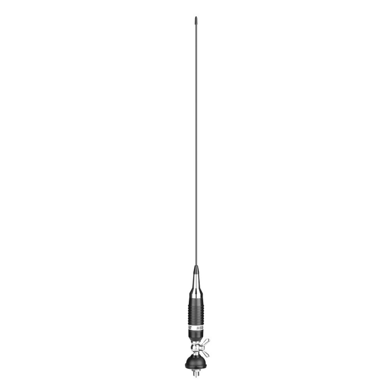
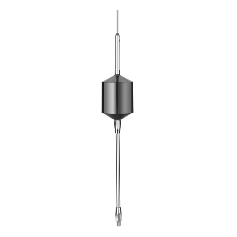
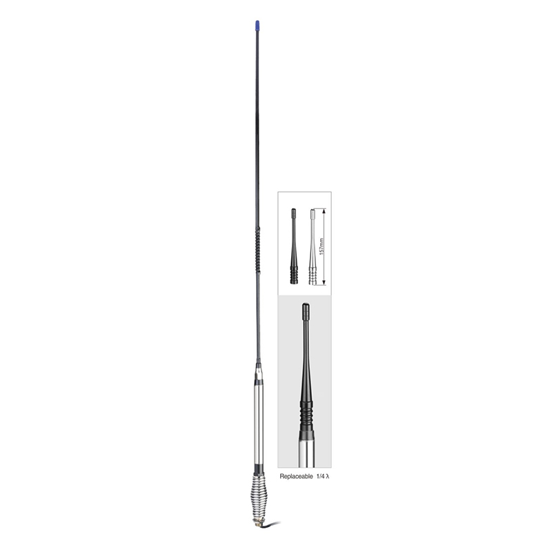
Frequency range: 26.5- 28MHz SWR: ≤1.2:1 Max. power: 35W continuous 250W Short time Bandwidth at S.W.R. 2:1: 1900KHz Impedance: 50ohm Whip length: 1200mm Adjustment: 0~90° Cable Length: RG58/157" Po...
See DetailsHow to get a good SWR?
An inappropriate ground plane is one of the major causes of high SWR readings. You should select a sound ground plane with an entire metal surface.
It would be to run the ground straps to as many parts of the vehicle's chassis as possible. Keep the straps as short as possible. The system should be grounded well with the plane so that readings can be normalized.
Improper installation and mounting of the antenna is another factor causing the problem. To avoid any loopholes, we advise that you mount the antenna as prescribed in the manual and ground every part of the CB system properly.
You can use a voltage meter to determine the vehicle's points that might hinder your system's grounding and then try to ground those parts to improve your ground plane.
A damaged coaxial cable is a big reason behind high SWR readings.
A coax can get twisted, shorted, or pinched while routing through the vehicle. It might come damaged when buying from the market. Hence it is essential to check your coax cable thoroughly before purchasing. Use a 50-ohm coax for single antennas and a 75-ohm coax for dual antennas.
POOR CB ANTENNA MOUNTING LOCATIONS
If you have achieved an SWR reading somewhere between 2.0 and 3.0, your system is not tuned correctly and needs to be dialed in better.
Another major factor in such high SWR readings is the poor location for mounting your CB antenna. Your mounting location is a poor one if it has the following characteristics:
The antenna is below the roofline.
The antenna is blocked or covered of the time.
The antenna is too close to metal buildings or structures.
If your mounting location has these three characteristics, change it immediately.
To get the out of your CB radio, you need an antenna that is properly tuned. Having a high SWR reading can not only cause interference on your CB radio, it can actually damage it. Here are some steps to test the standing wave ratio of your antenna system and tune it for performance.
Choose a clear, unobstructed location to adjust the SWR Antennas are very sensitive to objects close to them. Go to an open area to tune your antennae, such as a parking lot or remote field. This can also be done at home, provided you are not close to the house. Do not try to tune inside a building, under trees, near or under power lines, or with someone standing next to the antenna. This distorts the signal and causes a reflection back into the antenna giving false readings. Also, close all doors, the hood, and the trunk lid.
Setting the SWR Test with the radio only. If you have an amplifier, turn it off or preferably remove it from installation.
Insert the antenna whip into the chrome antenna adjustment mast at the top of the coil.
Using either the meter built into the radio or a good external SWR meter, calibrate on channel 20. Switch back to SWR and record the readings on three channels 1, 20, & 40.
If the SWR reading occurs on channel 1, the antenna length is too long and must be shortened. Loosen the mast set screws and lower the whip 1/4 into the mast. Tighten the mast set screw and again read SWR. Repeat until the SWR is obtained. If the whip is fully lowered into the mast and the SWR is still high, remove the whip from the mast. Using a hacksaw, grinder, or bolt cutters, cut 1/4 from the bottom part of the whip antenna. Re-insert the whip into the mast and test again for SWR. Repeat the above procedure until the SWR is below 1.5 of all channels.
If the SWR reading occurs on channel 40, the antenna whip is too short and must be raised. Loosen the mast set screws, raise the whip 1/4, re-tighten the set screws, and test SWR again. Repeat the above procedure until the SWR is below 1.5 of all channels
Common Causes of High SWR
A poor ground plane is often the cause of high SWR. Select a sound ground plane with an entire metal surface
It would be to run the ground straps to as many parts of the vehicle’s chassis as possible. Your goal should be to keep them as short as possible
Improper antenna installation and mounting of the antenna are other factors causing the problem. To avoid any ground loops, we advise you to mount the antenna exactly as instructed in the manual and ground every part of the CB antenna mount correctly
Use a voltage meter to determine the vehicle’s points that might hinder your system’s grounding, and then try to ground those parts to improve your ground plane
A damaged coaxial cable or PL-259 is a very common issue behind high antenna SWR readings. When troubleshooting, check for these damages, which are commonly found on fiberglass antennas
A coax can get twisted, shorted, or pinched while routing through the vehicle. It might come damaged when buying from the market. Hence it is essential to check your coax cable thoroughly before purchasing. Use a 50-ohm coax for single antennas and a 75-ohm coax for dual antennas
10 Steps To A Digital TV Antenna Installation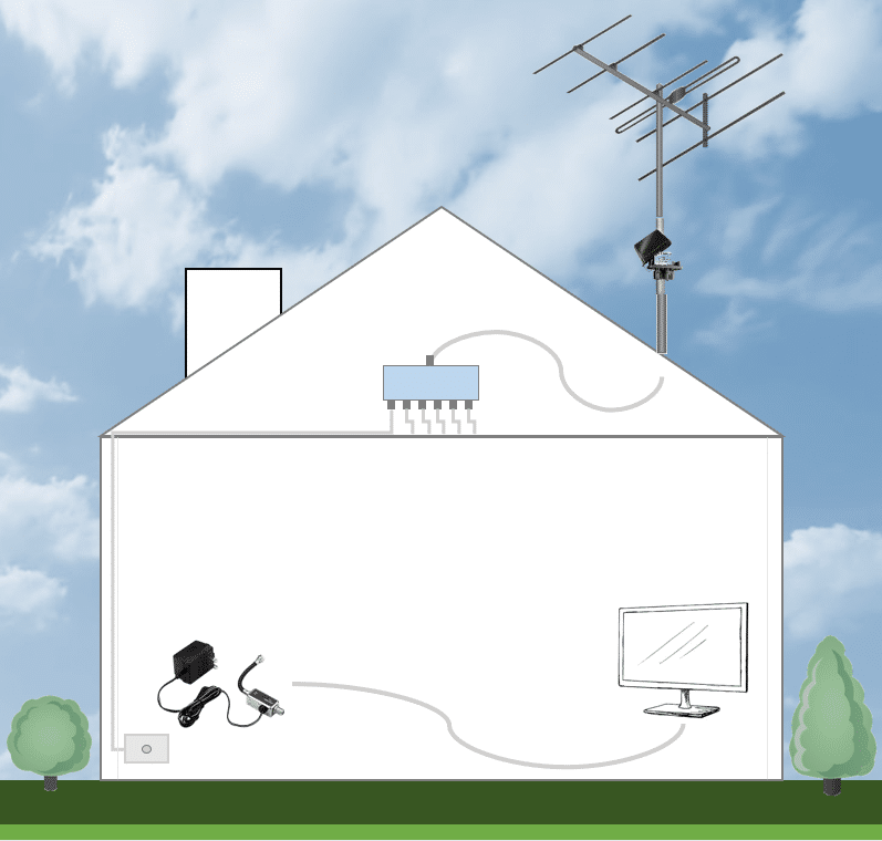
So the Free To Air TV reception at your house in Sydney has suddenly gone bad. The picture has started pixelating, it then skips a frame every now and then, and the audio is constantly breaking up. There is something wrong with your TV antenna system.
10 Steps to A Digital TV Antenna Installation in Sydney
In order to get your digital TV reception back up and running again, there are the following 10 steps you need for your digital TV antenna installation in Sydney to get that picture and audio back to again.
1. The Right TV Antenna
The important part of any residential TV antenna system is the TV antenna itself. If you are based in Sydney, you will need to check whether or not you need a VHF (Very High Frequency) or UHF (Ultra High Frequency) antenna. This will depend on which TV transmitter gives the signal in your local area. For a large part of Sydney, this will mean getting a VHF antenna and pointing it towards Artarmon in Sydney’s North. But if you are on the outskirts, or in a hilly area, there may be a different TV transmitter that provides better reception.
In addition, no matter if you pointing at a VHF or UHF transmitter, there are many different designs and sizes of antenna that will receive the signal better than others. For TV reception, the critical design element is the antenna’s ‘gain’. A high gain antenna will receive a stronger signal power and a better quality signal than a low gain antenna. You may also get an antenna with some degree of 4G or 5G filter built-in to assist in reducing noise or interference (see more details below).
2. The TV Antenna Mount or Mast and Antenna Alignment
The type of antenna mount you use can actually improve the quality of your reception due to one important factor – height. The height of antenna mount can make a HUGE difference to the signal quality and power you receive at your TV and is often the difference between having some reception or no reception. In some areas, where you have line of sight to the nearby signal transmitter, you will only need a short ~1.4m tin or tile roof mount. In other situations, you may need a 15ft guyed masted, or even up to a 50ft guyed mast. Yes, we still install 50ft (~15m) guyed mast on the top of 1 or 2 storey buildings. This can mean up to 70ft above ground level! Thankfully, with digital TV signals, this isn’t required nearly as much as back in the days of analogue TV.
In addition to the type of antenna mount, you will also need to consider the alignment of the antenna (to ensure it is pointing towards your desired transmitter) and placement of the antenna mount on your rooftop. There may be trees or foliage (or other tall buildings) you will want to avoid, whilst trying to get to the point on the roof for the reliable signal.
3. TV Antenna Booster (with 4G Filter)
Whether you have a VHF or UHF antenna, depending on your location, building height, number of TV outlets and type/length of cable runs, you may need a TV antenna booster.
Digital TV signal has two main components: (i) signal power; and (ii) signal quality. Whilst signal power can be adjusted with the assistance of a TV antenna booster (also called an antenna amplifier or TV signal booster), you cannot improve signal quality with any similar device.
Signal quality will be primarily determined at the antenna (type and location of the antenna). If you are experiencing poor signal quality, you will likely need to replace the antenna with a better one or relocate the antenna to a different location (normally higher) in order for it to receive more signal.
Signal power, on the other hand, can be increased with a TV antenna booster, or decreased with an attenuator. Signal power decreased for a number of reasons. You may be in a poor signal area (a long distance from the transmitter), have a large hill between your house and the transmitter, be splitting the signal between a number of TV outlets in your house, be using old high-loss cable, have long cable runs, or something else. There are many factors that contribute to signal loss in a TV system that results in the need to use a antenna booster to amplify the signal.
When using a TV antenna booster, there are 2 main things to lookout for.
The is that you do not want to overload the signal (by turning the amplifier up too high). TV tuners can only process signal when it is received within a specific signal power decibel (db) band. The TV tuner will not work with a signal power level that is too low, and will also not work with a signal power level that is too high!
The second warning is that a TV antenna booster does not know which signals are used for TV channels, as compared to AM radio, 4G mobile phone signals, or any other RF signal. As a result, it is important that you are not amplifying unwanted 4G signals that can cause interference with the TV signals which we want to isolate. As a result, many TV antenna boosters these days have in-built 4G / LTE filters.
4. -in Cable
The -in cable connects the antenna to the next device in your TV system, which is normally an antenna splitter located in your roofspace. The -in cable should be of the quality as it needs to keep signal levels as high as possible, and also needs to be weather (sun and rain) resistant.
As a result, we recommend the use of 50ohm quad shield RG6 or RG11 cable only. Four layers of shielding is the premium standard for TV cabling in Australia and ensures protection from the elements, but also ensures that there is no other unwanted RF signals entering our cable and causing interference.
5. High Isolation RF Splitter
The antenna splitter may look like a standard device, but beware of the small but subtle differences between the types of splitters available. The important feature is the frequency able to be passed through the splitter. Whilst Free To Air TV reception (VHF and UHF) all sit below 850Mhz, if you need your Foxtel reception to pass through the splitter, you may have to increase the quality of your splitter to pass up to 2400Mhz. In addition, you will want to look out for high isolation splitters, as they will result in one port of the splitter not having any impact on other ports, which can cause issues that are sometimes very difficult to locate.
Splitters come in various sizes, from a simple 2way splitter up to an 8way splitter. They can be ‘daisy-chained’ so as to serve more than 8 TV outlets from the one antenna, however, each time you split the signal, you lose signal power. So, in a system where the signal has been split, there is a greater chance of requiring a TV antenna booster in order to return the signal power back to a level that can be used by your TV tuner.
Finally, splitters can have certain ports that are ‘power pass’. This means that a small electrical current can be passed from the TV outlet up the TV cable to any booster that is normally located near the antenna. Boosters need power to operate, and so without the coaxial cable allowing electricity to pass through, and without a splitter that has ‘power pass’ ports, there is sometimes no way to get it powered up.
6. Outlet Cabling
Outlet cabling runs from your splitter to the TV outlet or wall plate. Depending on the type of cable used, there are distances that the signal power level will remain in tact before it becomes too low to work. If there is a very long cable run, you will need RG11 cable, otherwise, we recommend the use of a high quality quad-shield RG6 cable.
7. Wall Plates
Wall plates screw onto the wall (much like a power point) and allow you to plug in a short patch or fly from the TV to the wall. Wall plates don’t look like much, but comprise of a C-clip, the wall plate itself, a cover plate and a mechanism. They can come in a variety of colours and styles, so you can have a ‘double gang’ or ‘triple gang’ if you want more than one TV point in the one location, or you want to also have a data point on the same wall plate.
8. TV Booster Power Supply
TV boosters require power to operate – ie they are an ‘active’ device. Thankfully, we have a way to get power to them without placing a power point on your rooftop!
The coaxial cable that we install to send the signal from the antenna to your wall plate is actually capable of sending a very low electrical current in the opposite direction! The TV booster power injector and power supply is the device that ‘injects’ power into the cable and sends that power (normally 13V or 18V) up the coaxial cable, all the way up to your TV booster. As you already know, this will only work properly if you have a splitter with a ‘power pass’ port on the right cable!
9. TV Fly s
A TV fly is the short piece of cable that connects your TV to the TV wall plate. It should not be underestimated in terms of its importance, and we have had many situations in the past where a poor quality fly has caused many issues.
The thing to look out for are that the fly is made of high quality cable. Again, we recommend the use of quad-shield RG6 cable.
Secondly, you will not want the fly to be very long, or have many joins in the cable. Given fly s can sometimes be very low quality (especially those that come with the TV or that you can buy in your local electronics shop), you will want to make this cable as short as possible (no more than a few metres).
10. TV Tuner
The final piece of the puzzle to ensure you get digital TV reception is the TV tuner that sits inside your TV or set-top box. Whilst there are situations where you have a digital TV signal at the end of your TV fly , if the TV tuner in your TV is faulty or broken entirely, then you will not receive a reliable video/audio experience.
Unfortunately, with TV repairers few and far between, this means you can either buy a TV set-top box to perform the TV tuner function on behalf of your TV, or you will have to buy a whole new TV!
Antenna Separation Guide For Cell Phone Signal Boosters
Antenna separation when installing cell phone signal boosters is a recurrent theme that comes up from our customers and we
decided to do a post to clear some questions that can guide you in getting the out of your cell phone signal booster. Why separation is so crucial?
Separation is crucial because other wise the signals gets all crisscrossed and jumbled. The result is you having to deal with interference of cell phone signal, which means dropped calls and unwanted noise. The antennas are the loud mouths that enable the cell phone to talk to the towers that you see on highways,
those tall metal structures with dish antennas. All our cell phones have antennas as well but they are so small and hidden that you don't see. However the antennas are there and that is what enables you to make calls and receive calls. The cell phone
signal boosters have a donor antenna and receiver antenna. The donor antenna sends out signal, while the receiver antenna like the name suggests receives signal from the cell phone tower.
Now, as far as the antennas are concerned they are not intelligent devices that can distinguish they antenna at the cell phone tower or they antenna that is n your phone. They take the path of resistance , meaning they will talk to any antenna that is in their vicinity. If the two antennas are not separated then they are going to talk to each other.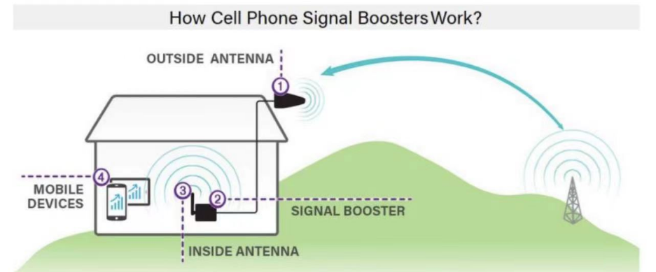
The outdoor antenna is physically separated from the indoor
antenna but to know how much , follow this simple guide below to obtain the optimum separation.
BOOSTER GAIN MIN. ANTENNA
(dB) SEPARATION
20 dB 3 feet
30 dB 4 feet
40 dB 6 feet
45 dB 15 feet
55 dB 55 feet
65 dB 70 feet
68 dB 80 feet
70 dB 110 feet
80 dB 125 feet
Note: The distance specified are straight line distance between the external antenna and internal antenna.
Alternate Methods
a) DIP switch
Al all cell phone signal boosters for home application have a DIP switch or Dials for amplifier adjustment, you can reduce or amplify the signal to get rid of interference , but it should also be noted that this method can reduce your coverage area.
b) Metal Sheets
This is another method where if you introduce a metal
preferably aluminum will act as a signal blocker between the two
antennas. Since metal are highly reflective with radio
frequencies, you can get rid of interference via introducing

 English
 Español



Contact Us